HTP!m Devlog 1: Team Assembly, Learning, and Execution
A lot has happened since the last devlog! I got a lot done on the HTP!m CONTROL base unit before all the wiring and electronics. Plus, I finalized the HTP!m MODCORE PCB design, ordered them on Friday night, and they arrived on Tuesday. I’ve already assembled one and the others are ready to be assembled soon; I may save some for my teammates to learn soldering if they’re interested. I’ve also begun to learn how to CAD and 3D print, and it’s been quite fun learning something new.
Let me tell you more about what I’ve been up to.
The Team
I have a team now! Last Sunday, we assembled the HTP!m team:
| Name | Roles |
|---|---|
| Shawn Duong | Team lead, project management, and everything in-between. |
| Noorulain Irshad | Miniatures, platform, wiring, and modeling. |
| Ivan Piceno | Web dev and any other types of help. |
| Akhil Devarasetty | Hacking, electrical, and any other types of help. |
| Jet Lin | Software and electronics. |
I took some time to finish our roadmap (the task board) with the details of our game plan and timeline. This week, I’ve instructed them to select the tasks they’d like to take on, make sure they’re equipped with the prerequisites, and alert me if they foresee the need for any support in regards to education, equipment, assistance, or anything else of that nature.
We’re meeting this Sunday and all subsequent Sundays to link up, recap, smooth out spikes, close out sprints, and start new sprints – you know, operate as a team. We have a tight timeline and a lot to do in October, so it’s especially important that I properly equip them to individually succeed so that our team as a whole succeeds in making this awesome project possible.
HTP!m MODCORE
Following up to the last devlog, I did – in fact – find time to tidy up the schematic before moving onto the PCB design:
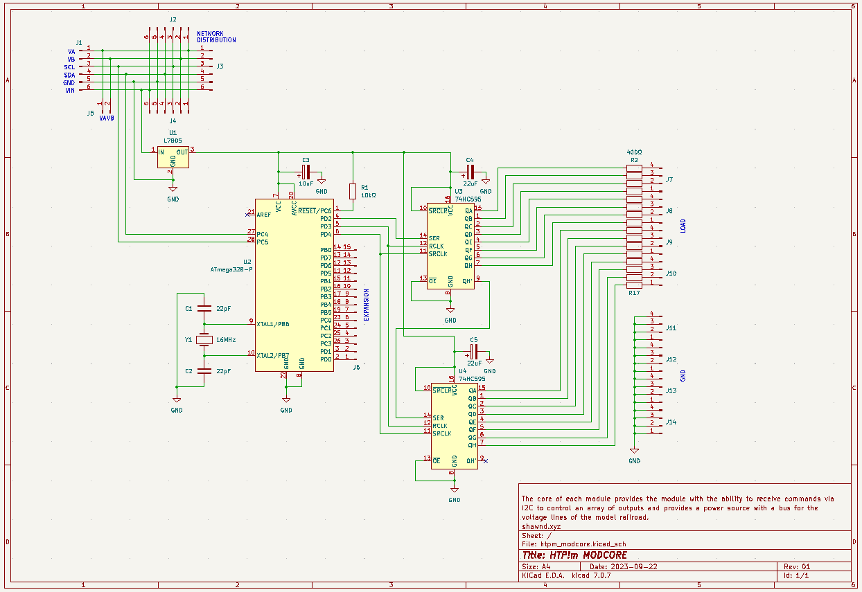
Much cleaner than the schematic I had before! It took me a long time to strategize how to best draw the schematic to communicate the ideas, be aesthetically clear and pleasant to view, and stay functional. I spent more time than I’d like to admit on refactoring the old schematic to the final schematic.
From the schematic, I designed the PCB. Again, this took more time than I’d like to admit. I went through revision after revision, trying different strategies and rearranging things in different ways, painstakingly routing traces manually to be clear and functional:
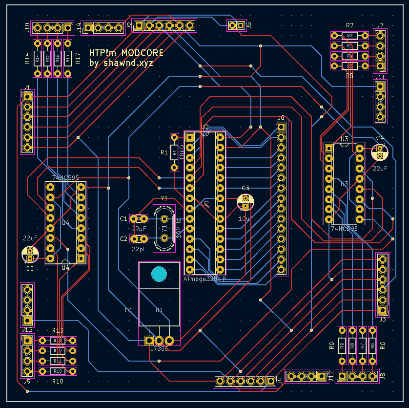
In the end, it was worth it. I put the order in on Friday night and they quickly arrived on Tuesday. I excitedly soldered one together and sent it to the team to marvel at:
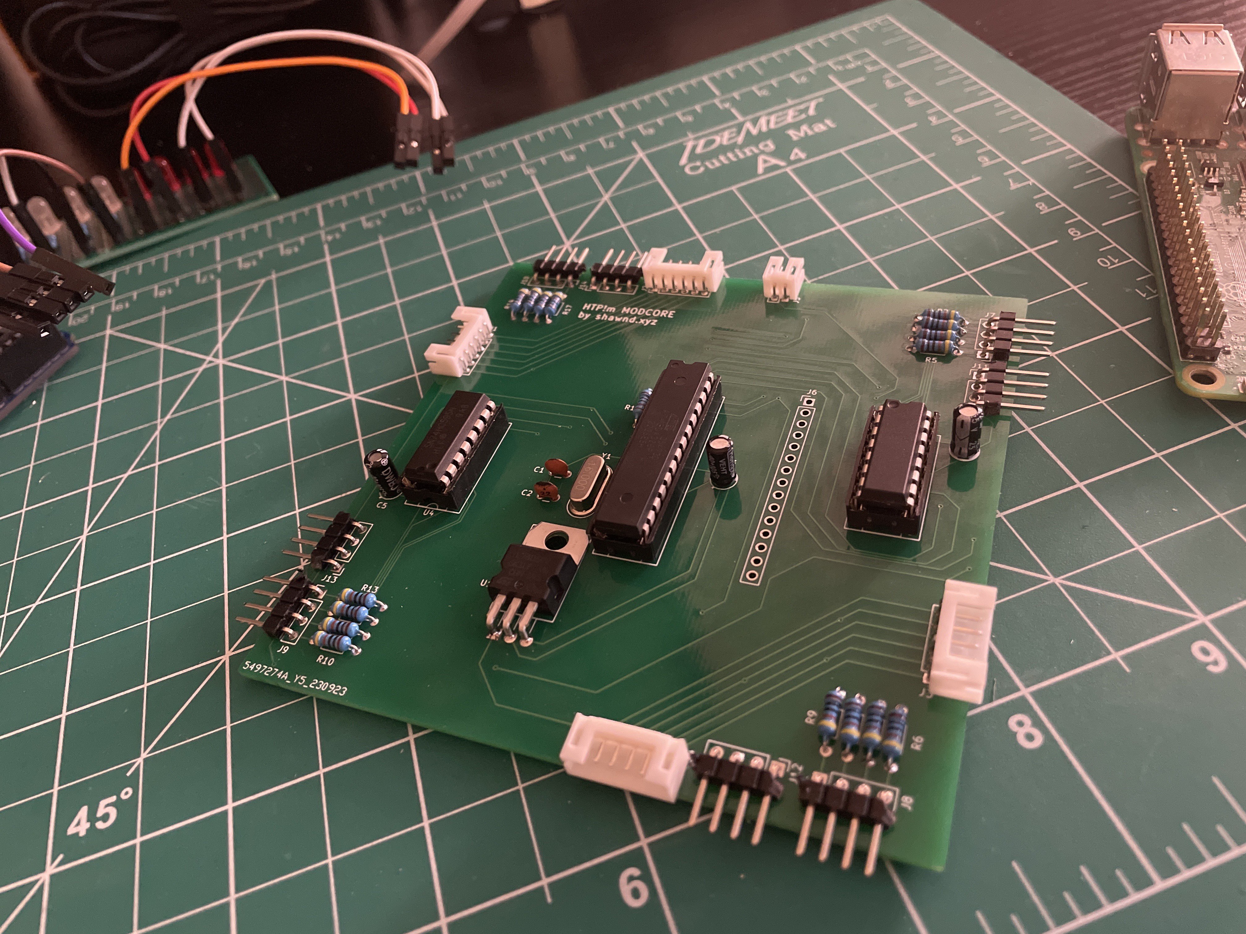
It might look fancy, but all that it really does is receive commands via I2C to control the actuation of 16 separate lines of power; it’s just a microcontroller and 2 shift registers, really. The HTP!m MODCORE also acts as a node in a power distribution network up to 0.5A for the rails, and allows the HTP!m CONTROL to apply [-12V, 12V] to the rails in order to control the locomotive.
HTP!m CONTROL
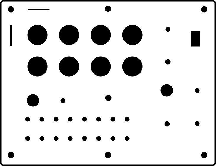
The HTP!m CONTROL is going well! With a whole lot of sweat and elbow work – and an ungodly amount of sanding and trial and error – I turned a 12” x 16” plastic sheet into a panel face to fit inside of the enclosure case. I used the mockup of the HTP!m CONTROL panel I created last week to create a “cutout” paper which I stuck to the trimmed sheet in order to drill and sand the slots I needed for all the knobs and buttons and switches:
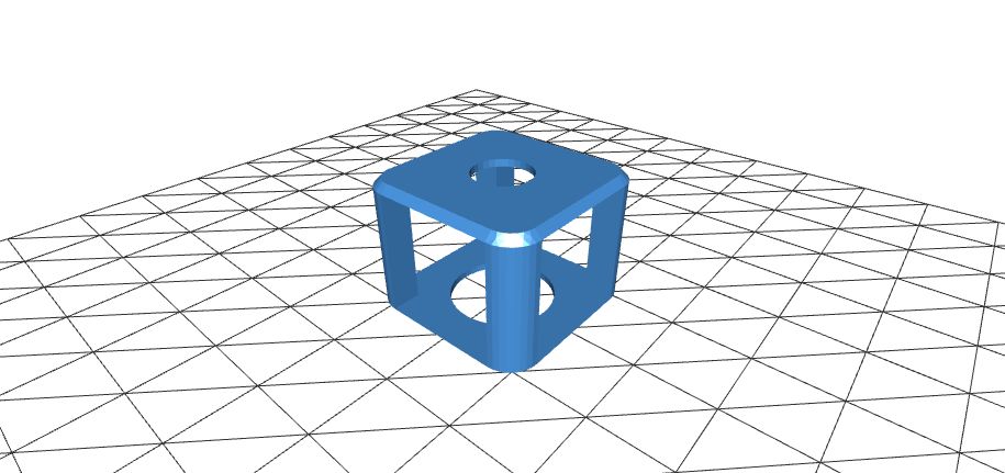
Because I didn’t want to drill anything into the enclosure itself in order to maintain its exterior aesthetic, I learned how to CAD and I 3D printed some mounting supports for the standoffs and glued them to the inside of the case. These allowed the standoffs to be supported and fixed to the bottom of the case without having to drill a hole through the exterior:
Using my label printer to finally annotate the panel after putting in all the components, the fruits of my labor were well worth it:
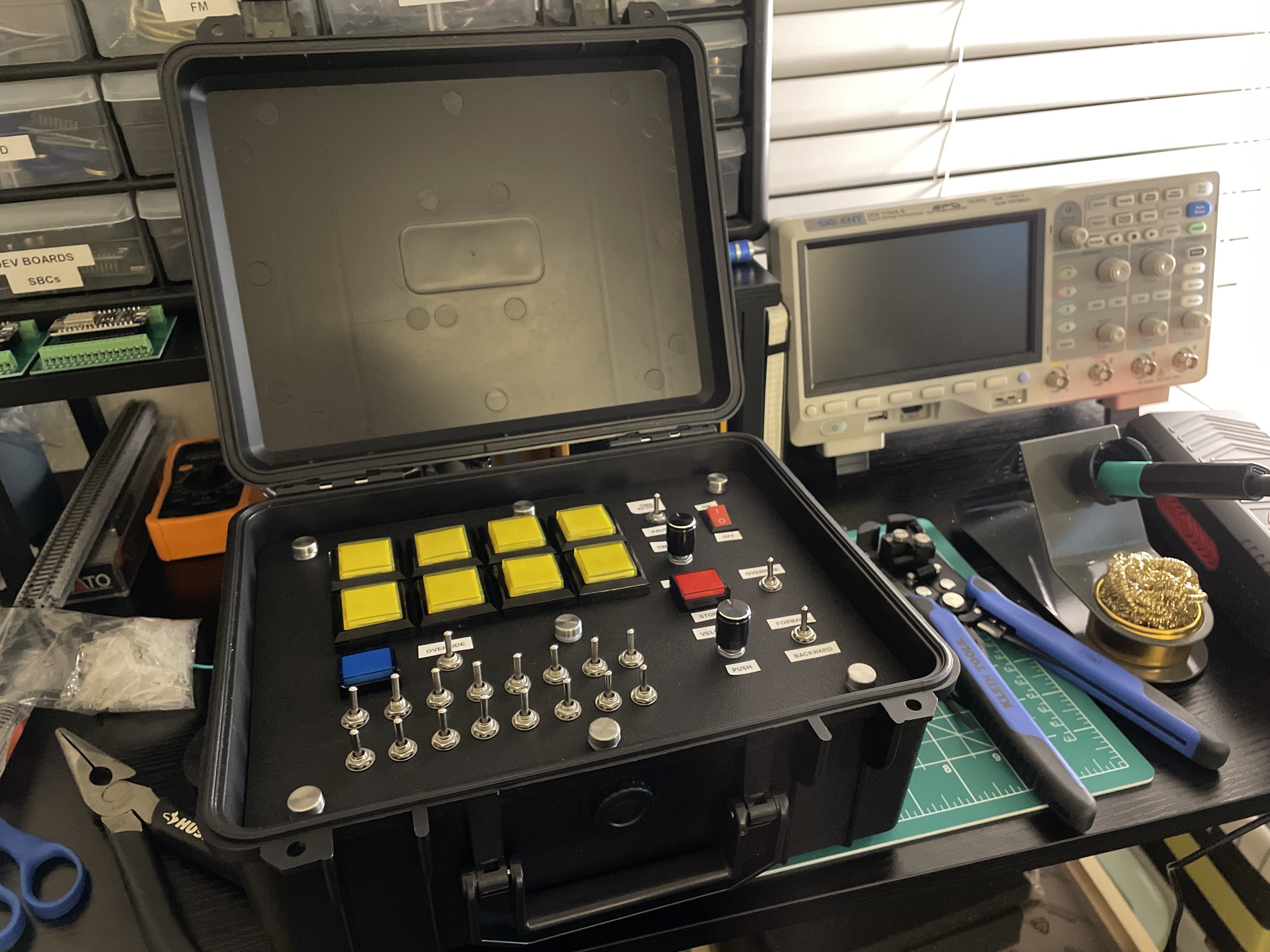
I still have a LOT of work to do on the HTP!m CONTROL, but I’m very satisfied with how cool it looks already. I have to wire the individual components, manage the cables, and create a PCB that will act as a hat on top of the Raspberry Pi; it’ll be connected to the panel as well as the display face, and essentially acts as a translation layer between the Pi and all the circuitry I need done for both the HTP!m CONTROL display face as well as the actual set.
I’m still exploring options for a connector between the ~50 individual pins from the control face and the hat circuit. I’m currently debating between a DB50 connector and a 50-pin IDC connector. I’m not sure quite yet, and that’s in the works.
I’m prototyping a whole bunch for the HTP!m CONTROL and I’ll likely have to pick up another Raspberry Pi or similar SBC for the HTP! CORE soon. More updates to follow. It’s been a busy week so far, and the weeks will only get busier.
Happy hacking!