HTP!m Devlog 2: Set Planning, Soldering, Firmware, and Web Dev
It’s been a great week since the last devlog! I finished planning a rough outline of the set, got together with the team to teach them soldering and assemble some HTP!m MODCOREs together, wrote the protocol for the message packets being sent over I2C, and started working on the web platform!
Set Planning
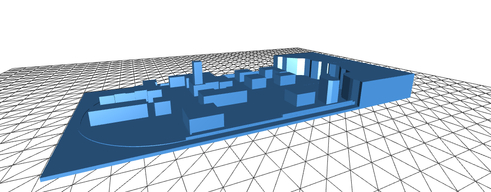
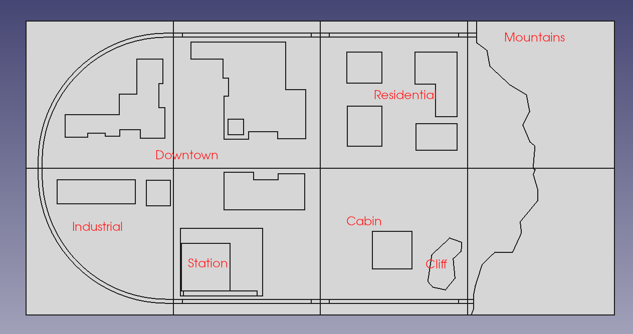
I’ve been addicted to 3D CADing lately. I’ve been learning FreeCAD as I go and have been having a lot of fun with expressing my ideas in 3 dimensions digitally. I created a 3D CAD of the rough set plan, making sure that the track has all the turning radius it needs to minimize the chances of malfunction as well as putting in some effort to include terrain and a moderately interesting city design:


I have some extruded polystyrene foam, hot wire cutting tools, and PPE coming in soon so I’ll hopefully be able to lay out the base by the end of the current sprint. The rails themselves came in earlier this week and the rail joiners are going to be on their way. For the buildings, we’re planning on CADing, 3d printing, and painting them into existence. Once the foam is cut, fitted, and glued to the frames, we can begin making terrain and laying out the set pieces as well as drilling holes for the wiring.
One of our teammates, Noor, is still exploring non-destructive solutions for module alignment. It’s a hard ask and is actually more difficult than one might think! If all else fails, we may need to fall back on the initial plan to (very carefully!) drill alignment holes between the frames and secure them with nuts and bolts.
The set isn’t realistic by any means, nor is it intending to be. We’re taking a lot of creative liberty, and that’s okay! If things are slightly out of scale or don’t make sense, that’s perfectly fine as long as our final product is working and we can be proud of having made it.
Soldering
Last Tuesday, I taught Ivan and Noor how to solder and we had a lot of fun doing a soldering sesh! Because they’re obviously not super experienced with soldering, it took quite a while for them to knock out two HTP!m MODCORE circuits between the two of them, and that’s perfectly fine because…
… now that they’re equipped with the skills to solder, I have 2 personnel to delegate assembly to for all the other circuits created as a part of this project. That’s time that they can spend improving and honing their skills and time that I can spend working on other tasks. We still have two more to assemble, so they’re coming back for a solder sesh part 2 later.

I have a few LED matrix PCBs that I’m going to be delegating to them in the weeks to come for assembly. We usually follow a pattern where I show them how to do a board and assemble an example, and they use that as a reference for subsequent assemblies. They’ve been doing great work, and I’m impressed with how fast they picked it up!
Firmware
I’ve been working on writing and refining the firmware for the HTP!m MODCORE units this week. During the prototyping phase, I was able to prove that I’d successfully wired them to be able to communicate via I2C and actuate up to 16 individual lines of power. At that point, I knew that my prototype worked and then created and designed the PCB. When the PCBs came in, I assembled a few and again verified that they were able to do what I needed them to do. In the interest of time and getting the PCBs sooner rather than later, I left more complex features like timers to be implemented in firmware later, and that “later” is now here.
I wrote a protocol specification for the messages being sent between the main and subs. Although I2C has its own error checking capabilities in most implementations, I made the decision to implement my own application-layer error checking and message validation in order to be assured of that. Because we don’t exactly need high-speed, there’s no reason why I wouldn’t want to assure my own requirements at the application layer.
Although I had initially designed the communication to be one-way (main-to-sub), I realized the need for two-way communication: if a module were to lose connection temporarily or reset unexpectedly, the main has no way of seeing its new reset state in order to push a state change to it again. For this reason, I picked up some I2C logic level converters to enable communication from the subs to the main and wrote specifications for some sub-to-main messages in the protocol. This logic level conversion would happen on one of the HTP!m CONTROL circuits, not on the HTP!m MODCORE units.
Some screenshots from my notes on the messaging protocol I wrote:

Plain and simple! The main has a MID array so it maintains MIDs for each sub individually. The main sends a message to a sub with the MID, the sub makes sure that it’s the MID that it’s expecting, and then the sub responds with the same MID in an ACK. If the sub doesn’t respond because the message was lost or corrupted, then it doesn’t do anything and the main will re-send based on a timer until it gets an ACK. If the main gets an ACK but it’s with a MID 0, then that implies that the sub must have had some kind of error where it reset and lost its state, and so the main will see this and send the sub its state again.
Because MIDs are 12 bits, we have a maximum MID of 4095 (inclusive). In order to handle overflow events, when a sub receives a message with MID 4095, the next MID it will expect will be 1. When the main receives an ACK with MID 4095, the next message it sends will have a MID of 1. We overflow to 1 – not 0 – in order to prevent the main getting confused and thinking that a sub has reset.
The implementation of this is about halfway done. While developing the firmware, I’m simultaneously developing code that can be used for the HTP!m CONTROL since I’m developing test scripts on the main in order to send data to the sub.
Web Dev
The web platform that players will use is well underway! One of my teammates, Jet, is taking the lead on that since he’s most comfortable doing web dev. I sent him the front-end mockup I did from before and made a diagram to help him understand the relationship between the audience, backend, database, and frontend:

He has a session scheduled with me this Saturday in order to work together on this. Although it’s assigned to this week’s sprint, the deadline isn’t until next week so it’s totally fine if this has to roll over.
Well, that’s all I have for you this week. I have a few essential ICs coming in tomorrow for prototyping and I still have a lot of wires to cut and crimp for the HTP!m CONTROL. I’m hoping to get the PCB for that done this week since it’s one of my sprint items. We have a hair under a month until “Hack the Planet! mini” debuts. There’s a lot of excitement to be had, and a lot of work to be done. Until next time,
Happy hacking!